|
|
Home | Switchboard | Unix Administration | Red Hat | TCP/IP Networks | Neoliberalism | Toxic Managers |
| (slightly skeptical) Educational society promoting "Back to basics" movement against IT overcomplexity and bastardization of classic Unix | |||||||
|
|
History of Internetworking
Internetworking Challenges
Open System Interconnection Reference Model
Characteristics of the OSI Layers
Protocols
OSI Model and Communication Between Systems
Interaction Between OSI Model Layers
OSI Layer Services
OSI Model Layers and Information Exchange
OSI Model Physical Layer
OSI Model Data Link Layer
OSI Model Network Layer
OSI Model Transport Layer
OSI Model Session Layer
OSI Model Presentation Layer
OSI Model Application Layer
Information Formats
ISO Hierarchy of Networks
Connection-Oriented and Connectionless Network Services
Internetwork Addressing
Data Link Layer Addresses
Flow Control Basics
Error-Checking Basics
Multiplexing Basics
Standards Organizations
Summary
Review Questions
For More Information
|
|
This chapter works with the next six chapters to act as a foundation for the technology discussions that follow. In this
chapter, some fundamental concepts and terms used in the evolving language of internetworking are addressed. In the same
way that this book provides a foundation for understanding modern networking, this chapter summarizes some common themes
presented throughout the remainder of this book. Topics include flow control, error checking, and multiplexing, but this
chapter focuses mainly on mapping the Open System Interconnection (OSI) model to networking/internetworking functions, and
also summarizing the general nature of addressing schemes within the context
of the OSI model. The OSI model represents the building blocks for internetworks. Understanding the conceptual model helps
you understand the complex pieces that make up an internetwork.
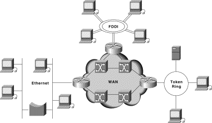
Figure 1-1: Different Network Technologies Can Be Connected to Create an Internetwork
The first networks were time-sharing networks that used mainframes and attached terminals. Such environments were implemented by both IBM's Systems Network Architecture (SNA) and Digital's network architecture.
Local-area networks (LANs) evolved around the PC revolution. LANs enabled multiple users in a relatively small geographical area to exchange files and messages, as well as access shared resources such as file servers and printers.
Today, high-speed LANs and switched internetworks are becoming widely used, largely because they operate at very high speeds and support such high-bandwidth applications as multimedia and videoconferencing.
Internetworking evolved as a solution to three key problems: isolated LANs, duplication
of resources, and a lack of network management. Isolated LANs made electronic
communication between different offices or departments impossible. Duplication of
resources meant that the same hardware and software had to be supplied to each office or department, as did separate support
staff. This lack of network management meant that no centralized method of managing and troubleshooting networks existed.
The challenge when connecting various systems is to support communication among disparate technologies. Different sites, for example, may use different types of media operating at varying speeds, or may even include different types of systems that need to communicate.
Because companies rely heavily on data communication, internetworks must provide a certain level of reliability. This is an unpredictable world, so many large internetworks include redundancy to allow for communication even when problems occur.
Furthermore, network management must provide centralized support and troubleshooting capabilities in an internetwork. Configuration, security, performance, and other issues must be adequately addressed for the internetwork to function smoothly. Security within an internetwork is essential. Many people think of network security from the perspective of protecting the private network from outside attacks. However, it is just as important to protect the network from internal attacks, especially because most security breaches come from inside. Networks must also be secured so that the internal network cannot be used as a tool to attack other external sites.
Early in the year 2000, many major web sites were the victims of distributed denial of service (DDOS) attacks. These attacks were possible because a great number of private networks currently connected with the Internet were not properly secured. These private networks were used as tools for the attackers.
Because nothing in this world is stagnant, internetworks must be flexible enough to change with new demands.
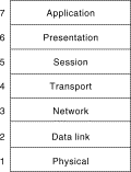
The Open System Interconnection (OSI) reference model describes how information from a software application in one computer moves through a network medium to a software application in another computer. The OSI reference model is a conceptual model composed of seven layers, each specifying particular network functions. The model was developed by the International Organization for Standardization (ISO) in 1984, and it is now considered the primary architectural model for intercomputer communications. The OSI model divides the tasks involved with moving information between networked computers into seven smaller, more manageable task groups. A task or group of tasks is then assigned to each of the seven OSI layers. Each layer is reasonably self-contained so that the tasks assigned to each layer can be implemented independently. This enables the solutions offered by one layer to be updated without adversely affecting the other layers. The following list details the seven layers of the Open System Interconnection (OSI) reference model:
Figure 1-2 illustrates the seven-layer OSI reference model.
Figure 1-2: The OSI Reference Model Contains Seven Independent Layers
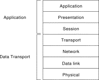
The upper layers of the OSI model deal with application issues and generally are implemented only in software. The highest layer, the application layer, is closest to the end user. Both users and application layer processes interact with software applications that contain a communications component. The term upper layer is sometimes used to refer to any layer above another layer in the OSI model.
The lower layers of the OSI model handle data transport issues. The physical layer and the data link layer are implemented in hardware and software. The lowest layer, the physical layer, is closest to the physical network medium (the network cabling, for example) and is responsible for actually placing information on the medium.
Figure 1-3 illustrates the division between the upper and lower OSI layers.
Figure 1-3: Two Sets of Layers Make Up the OSI Layers
The OSI model provides a conceptual framework for communication between computers, but the model itself is not a method of communication. Actual communication is made possible by using communication protocols. In the context of data networking, a protocol is a formal set of rules and conventions that governs how computers exchange information over a network medium. A protocol implements the functions of one or more of the OSI layers.
A wide variety of communication protocols exist. Some of these protocols include LAN protocols, WAN protocols, network protocols, and routing protocols. LAN protocols operate at the physical and data link layers of the OSI model and define communication over the various LAN media. WAN protocols operate at the lowest three layers of the OSI model and define communication over the various wide-area media. Routing protocols are network layer protocols that are responsible for exchanging information between routers so that the routers can select the proper path for network traffic. Finally, network protocols are the various upper-layer protocols that exist in a given protocol suite. Many protocols rely on others for operation. For example, many routing protocols use network protocols to exchange information between routers. This concept of building upon the layers already in existence is the foundation of the OSI model.
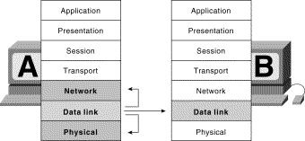
Information being transferred from a software application in one computer system to a software application in another must pass through the OSI layers. For example, if a software application in System A has information to transmit to a software application in System B, the application program in System A will pass its information to the application layer (Layer 7) of System A. The application layer then passes the information to the presentation layer (Layer 6), which relays the data to the session layer (Layer 5), and so on down to the physical layer (Layer 1). At the physical layer, the information is placed on the physical network medium and is sent across the medium to System B. The physical layer of System B removes the information from the physical medium, and then its physical layer passes the information up to the data link layer (Layer 2), which passes it to the network layer (Layer 3), and so on, until it reaches the application layer (Layer 7) of System B. Finally, the application layer of System B passes the information to the recipient application program to complete the communication process.
Figure 1-4: OSI Model Layers Communicate with Other Layers
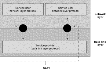
One OSI layer communicates with another layer to make use of the services provided by the second layer. The services provided by adjacent layers help a given OSI layer communicate with its peer layer in other computer systems. Three basic elements are involved in layer services: the service user, the service provider, and the service access point (SAP).
In this context, the service user is the OSI layer that requests services from an adjacent OSI layer. The service provider is the OSI layer that provides services to service users. OSI layers can provide services to multiple service users. The SAP is a conceptual location at which one OSI layer can request the services of another OSI layer.
Figure 1-5 illustrates how these three elements interact at the network and data link layers.
Figure 1-5: Service Users, Providers, and SAPs Interact at the Network and Data Link Layers
Control information typically takes one of two forms: headers and trailers. Headers are prepended to data that has been passed down from upper layers. Trailers are appended to data that has been passed down from upper layers. An OSI layer is not required to attach a header or a trailer to data from upper layers.
Headers, trailers, and data are relative concepts, depending on the layer that analyzes the information unit. At the network layer, for example, an information unit consists of a Layer 3 header and data. At the data link layer, however, all the information passed down by the network layer (the Layer 3 header and the data) is treated as data.
In other words, the data portion of an information unit at a given OSI layer potentially
can contain headers, trailers, and data from all the higher layers. This is known as encapsulation.
Figure 1-6 shows how the header and data from one layer are encapsulated into the header of the next lowest layer.
Figure 1-6: Headers and Data Can Be Encapsulated During Information Exchange

The information exchange process occurs between peer OSI layers. Each layer in the source system adds control information to data, and each layer in the destination system analyzes and removes the control information from that data.
If System A has data from a software application to send to System B, the data is passed to the application layer. The application layer in System A then communicates any control information required by the application layer in System B by prepending a header to the data. The resulting information unit (a header and the data) is passed to the presentation layer, which prepends its own header containing control information intended for the presentation layer in System B. The information unit grows in size as each layer prepends its own header (and, in some cases, a trailer) that contains control information to be used by its peer layer in System B. At the physical layer, the entire information unit is placed onto the network medium.
The physical layer in System B receives the information unit and passes it to the data link layer. The data link layer in System B then reads the control information contained in the header prepended by the data link layer in System A. The header is then removed, and the remainder of the information unit is passed to the network layer. Each layer performs the same actions: The layer reads the header from its peer layer, strips it off, and passes the remaining information unit to the next highest layer. After the application layer performs these actions, the data is passed to the recipient software application in System B, in exactly the form in which it was transmitted by the application in System A.
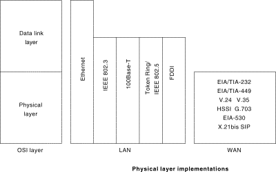
Figure 1-7: Physical Layer Implementations Can Be LAN or WAN Specifications
The data link layer provides reliable transit of data across a physical network link. Different data link layer specifications define different network and protocol characteristics, including physical addressing, network topology, error notification, sequencing of frames, and flow control. Physical addressing (as opposed to network addressing) defines how devices are addressed at the data link layer. Network topology consists of the data link layer specifications that often define how devices are to be physically connected, such as in a bus or a ring topology. Error notification alerts upper-layer protocols that a transmission error has occurred, and the sequencing of data frames reorders frames that are transmitted out of sequence. Finally, flow control moderates the transmission of data so that the receiving device is not overwhelmed with more traffic than it can handle at one time.
Figure 1-8: The Data Link Layer Contains Two Sublayers
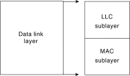
The Logical Link Control (LLC) sublayer of the data link layer manages communications between devices over a single link of a network. LLC is defined in the IEEE 802.2 specification and supports both connectionless and connection-oriented services used by higher-layer protocols. IEEE 802.2 defines a number of fields in data link layer frames that enable multiple higher-layer protocols to share a single physical data link. The Media Access Control (MAC) sublayer of the data link layer manages protocol access to the physical network medium. The IEEE MAC specification defines MAC addresses, which enable multiple devices to uniquely identify one another at the data link layer.
The transport layer accepts data from the session layer and segments the data for transport across the network. Generally, the transport layer is responsible for making sure that the data is delivered error-free and in the proper sequence. Flow control generally occurs at the transport layer.
Flow control manages data transmission between devices so that the transmitting device does not send more data than the receiving device can process. Multiplexing enables data from several applications to be transmitted onto a single physical link. Virtual circuits are established, maintained, and terminated by the transport layer. Error checking involves creating various mechanisms for detecting transmission errors, while error recovery involves acting, such as requesting that data be retransmitted, to resolve any errors that occur.
The transport protocols used on the Internet are TCP and UDP.
The session layer establishes, manages, and terminates communication sessions. Communication sessions consist of service requests and service responses that occur between applications located in different network devices. These requests and responses are coordinated by protocols implemented at the session layer. Some examples of session-layer implementations include Zone Information Protocol (ZIP), the AppleTalk protocol that coordinates the name binding process; and Session Control Protocol (SCP), the DECnet Phase IV session layer protocol.
The presentation layer provides a variety of coding and conversion functions that are applied to application layer data. These functions ensure that information sent from the application layer of one system would be readable by the application layer of another system. Some examples of presentation layer coding and conversion schemes include common data representation formats, conversion of character representation formats, common data compression schemes, and common data encryption schemes.
Common data representation formats, or the use of standard image, sound, and video formats, enable the interchange of application data between different types of computer systems. Conversion schemes are used to exchange information with systems by using different text and data representations, such as EBCDIC and ASCII. Standard data compression schemes enable data that is compressed at the source device to be properly decompressed at the destination. Standard data encryption schemes enable data encrypted at the source device to be properly deciphered at the destination.
Presentation layer implementations are not typically associated with a particular protocol stack. Some well-known standards for video include QuickTime and Motion Picture Experts Group (MPEG). QuickTime is an Apple Computer specification for video and audio, and MPEG is a standard for video compression and coding.
Among the well-known graphic image formats are Graphics Interchange Format (GIF), Joint Photographic Experts Group (JPEG), and Tagged Image File Format (TIFF). GIF is a standard for compressing and coding graphic images. JPEG is another compression and coding standard for graphic images, and TIFF is a standard coding format for graphic images.
The application layer is the OSI layer closest to the end user, which means that both the OSI application layer and the user interact directly with the software application.
This layer interacts with software applications that implement a communicating component. Such application programs fall outside the scope of the OSI model. Application layer functions typically include identifying communication partners, determining resource availability, and synchronizing communication.
When identifying communication partners, the application layer determines the identity and availability of communication
partners for an application with data to transmit.
When determining resource availability, the application layer must decide whether sufficient network resources for the requested
communication exist. In synchronizing communication, all communication between applications requires cooperation that is
managed by the application layer.
Some examples of application layer implementations include Telnet, File Transfer Protocol (FTP), and Simple Mail Transfer Protocol (SMTP).
The data and control information that is transmitted through internetworks takes a variety of forms. The terms used to
refer to these information formats are not used consistently
in the internetworking industry but sometimes are used interchangeably. Common information formats include frames, packets,
datagrams, segments, messages, cells, and data units.
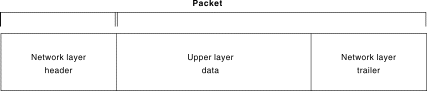
A frame is an information unit whose source and destination are data link layer entities. A frame is composed of the data link layer header (and possibly a trailer) and upper-layer data. The header and trailer contain control information intended for the data link layer entity in the destination system. Data from upper-layer entities is encapsulated in the data link layer header and trailer. Figure 1-9 illustrates the basic components of a data link layer frame.
Figure 1-9: Data from Upper-Layer Entities Makes Up the Data Link Layer Frame
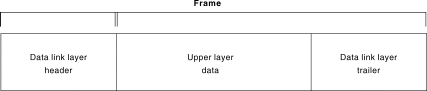
Figure 1-10: Three Basic Components Make Up a Network Layer Packet
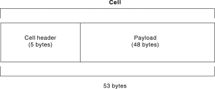
A cell is an information unit of a fixed size whose source and destination are data link layer entities. Cells
are used in switched environments, such as Asynchronous Transfer Mode (ATM) and Switched Multimegabit
Data Service (SMDS) networks. A cell is composed
of the header and payload. The header contains control information intended for the destination data
link layer entity and is typically 5 bytes long. The payload contains upper-layer data that is encapsulated in the cell
header and is typically 48 bytes long.
The length of the header and the payload fields always are the same for each cell.
Figure 1-11 depicts the components of a typical cell.
Figure 1-11: Two Components Make Up a Typical Cell
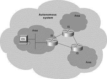
Large networks typically are organized as hierarchies. A hierarchical organization provides such advantages as ease of management, flexibility, and a reduction in unnecessary traffic. Thus, the International Organization for Standardization (ISO) has adopted a number of terminology conventions for addressing network entities. Key terms defined in this section include end system (ES), intermediate system (IS), area, and autonomous system (AS).
An ES is a network device that does not perform routing or other traffic forwarding functions. Typical ESs include such devices as terminals, personal computers, and printers. An IS is a network device that performs routing or other traffic-forwarding functions. Typical ISs include such devices as routers, switches, and bridges. Two types of IS networks exist: intradomain IS and interdomain IS. An intradomain IS communicates within a single autonomous system, while an interdomain IS communicates within and between autonomous systems. An area is a logical group of network segments and their attached devices. Areas are subdivisions of autonomous systems (AS's). An AS is a collection of networks under a common administration that share a common routing strategy. Autonomous systems are subdivided into areas, and an AS is sometimes called a domain. Figure 1-12 illustrates a hierarchical network and its components.
Figure 1-12: A Hierarchical Network Contains Numerous Components
In general, transport protocols can be characterized as being either connection-oriented or connectionless. Connection-oriented services must first establish a connection with the desired service before passing any data. A connectionless service can send the data without any need to establish a connection first. In general, connection-oriented services provide some level of delivery guarantee, whereas connectionless services do not.
Connection-oriented service involves three phases: connection establishment, data transfer, and connection termination.
During connection establishment, the end nodes may reserve resources for the connection. The end nodes also may negotiate and establish certain criteria for the transfer, such as a window size used in TCP connections. This resource reservation is one of the things exploited in some denial of service (DOS) attacks. An attacking system will send many requests for establishing a connection but then will never complete the connection. The attacked computer is then left with resources allocated for many never-completed connections. Then, when an end node tries to complete an actual connection, there are not enough resources for the valid connection.
The data transfer phase occurs when the actual data is transmitted over the connection. During data transfer, most connection-oriented services will monitor for lost packets and handle resending them. The protocol is generally also responsible for putting the packets in the right sequence before passing the data up the protocol stack.
When the transfer of data is complete, the end nodes terminate the connection and release resources reserved for the connection.
Connection-oriented network services have more overhead than connectionless ones. Connection-oriented services must negotiate a connection, transfer data, and tear down the connection, whereas a connectionless transfer can simply send the data without the added overhead of creating and tearing down a connection. Each has its place in internetworks.
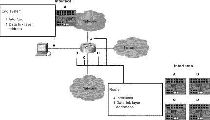
A data link layer address uniquely identifies each physical network connection of a network device. Data-link addresses sometimes are referred to as physical or hardware addresses. Data-link addresses usually exist within a flat address space and have a pre-established and typically fixed relationship to a specific device.
End systems generally have only one physical network connection and thus have only one data-link address. Routers and other internetworking devices typically have multiple physical network connections and therefore have multiple data-link addresses. Figure 1-13 illustrates how each interface on a device is uniquely identified by a data-link address.
Figure 1-13: Each Interface on a Device Is Uniquely Identified by a Data-Link Address.
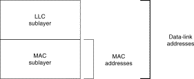
Media Access Control (MAC) addresses consist of a subset of data link layer addresses. MAC addresses identify network entities in LANs that implement the IEEE MAC addresses of the data link layer. As with most data-link addresses, MAC addresses are unique for each LAN interface. Figure 1-14 illustrates the relationship between MAC addresses, data-link addresses, and the IEEE sublayers of the data link layer.
Figure 1-14: MAC Addresses, Data-Link Addresses, and the IEEE Sublayers of the Data Link Layer Are All Related
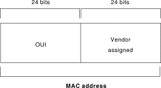
MAC addresses are 48 bits in length and are expressed as 12 hexadecimal digits. The first 6 hexadecimal digits, which are administered by the IEEE, identify the manufacturer or vendor and thus comprise the Organizationally Unique Identifier (OUI). The last 6 hexadecimal digits comprise the interface serial number, or another value administered by the specific vendor. MAC addresses sometimes are called burned-in addresses (BIAs) because they are burned into read-only memory (ROM) and are copied into random-access memory (RAM) when the interface card initializes. Figure 1-15 illustrates the MAC address format.
Figure 1-15: The MAC Address Contains a Unique Format of Hexadecimal Digits
Because internetworks generally use network addresses to route traffic around the network, there is a need to map network addresses to MAC addresses. When the network layer has determined the destination station's network address, it must forward the information over a physical network using a MAC address. Different protocol suites use different methods to perform this mapping, but the most popular is Address Resolution Protocol (ARP).
Different protocol suites use different methods for determining the MAC address of a device. The following three methods are used most often. Address Resolution Protocol (ARP) maps network addresses to MAC addresses. The Hello protocol enables network devices to learn the MAC addresses of other network devices. MAC addresses either are embedded in the network layer address or are generated by an algorithm.
Address Resolution Protocol (ARP) is the method used in the TCP/IP suite. When a network device needs to send data to another device on the same network, it knows the source and destination network addresses for the data transfer. It must somehow map the destination address to a MAC address before forwarding the data. First, the sending station will check its ARP table to see if it has already discovered this destination station's MAC address. If it has not, it will send a broadcast on the network with the destination station's IP address contained in the broadcast. Every station on the network receives the broadcast and compares the embedded IP address to its own. Only the station with the matching IP address replies to the sending station with a packet containing the MAC address for the station. The first station then adds this information to its ARP table for future reference and proceeds to transfer the data.
When the destination device lies on a remote network, one beyond a router, the process is the same except that the sending station sends the ARP request for the MAC address of its default gateway. It then forwards the information to that device. The default gateway will then forward the information over whatever networks necessary to deliver the packet to the network on which the destination device resides. The router on the destination device's network then uses ARP to obtain the MAC of the actual destination device and delivers the packet.
Three protocols use predictable MAC addresses. In these protocol suites, MAC addresses are predictable because the network layer either embeds the MAC address in the network layer address or uses an algorithm to determine the MAC address. The three protocols are Xerox Network Systems (XNS), Novell Internetwork Packet Exchange (IPX), and DECnet Phase IV.
A network layer address identifies an entity at the network layer of the OSI layers. Network addresses usually exist within a hierarchical address space and sometimes are called virtual or logical addresses.
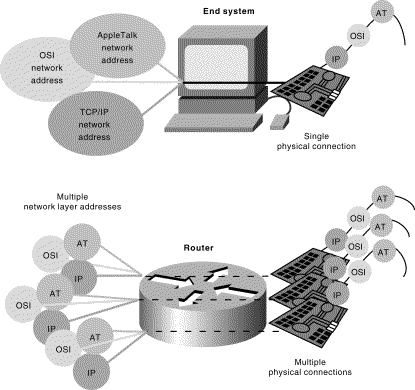
The relationship between a network address and a device is logical and unfixed; it typically is based either on physical network characteristics (the device is on a particular network segment) or on groupings that have no physical basis (the device is part of an AppleTalk zone). End systems require one network layer address for each network layer protocol that they support. (This assumes that the device has only one physical network connection.) Routers and other internetworking devices require one network layer address per physical network connection for each network layer protocol supported. For example, a router with three interfaces each running AppleTalk, TCP/IP, and OSI must have three network layer addresses for each interface. The router therefore has nine network layer addresses. Figure 1-16 illustrates how each network interface must be assigned a network address for each protocol supported.
Figure 1-16: Each Network Interface Must Be Assigned a Network Address for Each Protocol Supported
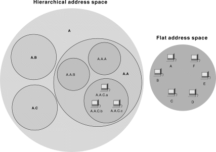
Internetwork address space typically takes one of two forms: hierarchical address space or flat address space. A hierarchical address space is organized into numerous subgroups, each successively narrowing an address until it points to a single device (in a manner similar to street addresses). A flat address space is organized into a single group (in a manner similar to U.S. Social Security numbers).
Hierarchical addressing offers certain advantages over flat-addressing schemes. Address sorting and recall is simplified using comparison operations. For example, "Ireland" in a street address eliminates any other country as a possible location. Figure 1-17 illustrates the difference between hierarchical and flat address spaces.
Figure 1-17: Hierarchical and Flat Address Spaces Differ in Comparison Operations
Addresses are assigned to devices as one of two types: static and dynamic. Static addresses
are assigned by a network administrator according to a preconceived internetwork addressing plan. A static address does
not change until the network administrator manually changes it. Dynamic addresses are obtained
by devices when they attach to a network, by means of some protocol-specific process. A device using a dynamic address often
has a different address each time that it connects to the network. Some networks use a server to assign
addresses. Server-assigned addresses are recycled for reuse as devices disconnect.
A device is therefore likely to have a different address each time that it connects to the network.
Internetwork devices usually have both a name and an address associated with them. Internetwork names typically are location-independent and remain associated with a device wherever that device moves (for example, from one building to another). Internetwork addresses usually are location-dependent and change when a device is moved (although MAC addresses are an exception to this rule). As with network addresses being mapped to MAC addresses, names are usually mapped to network addresses through some protocol. The Internet uses Domain Name System (DNS) to map the name of a device to its IP address. For example, it's easier for you to remember www.cisco.com instead of some IP address. Therefore, you type www.cisco.com into your browser when you want to access Cisco's web site. Your computer performs a DNS lookup of the IP address for Cisco's web server and then communicates with it using the network address.
Flow control is a function that prevents network congestion by ensuring that transmitting devices do not overwhelm receiving devices with data. A high-speed computer, for example, may generate traffic faster than the network can transfer it, or faster than the destination device can receive and process it. The three commonly used methods for handling network congestion are buffering, transmitting source-quench messages, and windowing.
Windowing is a flow-control scheme in which the source device requires an acknowledgment from the destination after a certain number of packets have been transmitted. With a window size of 3, the source requires an acknowledgment after sending three packets, as follows. First, the source device sends three packets to the destination device. Then, after receiving the three packets, the destination device sends an acknowledgment to the source. The source receives the acknowledgment and sends three more packets. If the destination does not receive one or more of the packets for some reason, such as overflowing buffers, it does not receive enough packets to send an acknowledgment. The source then retransmits the packets at a reduced transmission rate.
One common error-checking scheme is the cyclic redundancy check (CRC), which detects and discards corrupted data. Error-correction functions (such as data retransmission) are left to higher-layer protocols. A CRC value is generated by a calculation that is performed at the source device. The destination device compares this value to its own calculation to determine whether errors occurred during transmission. First, the source device performs a predetermined set of calculations over the contents of the packet to be sent. Then, the source places the calculated value in the packet and sends the packet to the destination. The destination performs the same predetermined set of calculations over the contents of the packet and then compares its computed value with that contained in the packet. If the values are equal, the packet is considered valid. If the values are unequal, the packet contains errors and is discarded.
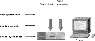
Multiplexing is a process in which multiple data channels are combined into a single data or physical channel at the source. Multiplexing can be implemented at any of the OSI layers. Conversely, demultiplexing is the process of separating multiplexed data channels at the destination. One example of multiplexing is when data from multiple applications is multiplexed into a single lower-layer data packet. Figure 1-18 illustrates this example.
Figure 1-18: Multiple Applications Can Be Multiplexed into a Single Lower-Layer Data Packet
Another example of multiplexing is when data from multiple devices is combined into a single physical channel (using a device called a multiplexer). Figure 1-19 illustrates this example.
Figure 1-19: Multiple Devices Can Be Multiplexed into a Single Physical Channel
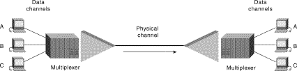
A multiplexer is a physical layer device that combines multiple data streams into one or more output channels at the source. Multiplexers demultiplex the channels into multiple data streams at the remote end and thus maximize the use of the bandwidth of the physical medium by enabling it to be shared by multiple traffic sources.
Some methods used for multiplexing data are time-division multiplexing (TDM), asynchronous time-division multiplexing (ATDM), frequency-division multiplexing (FDM), and statistical multiplexing.
In TDM, information from each data channel is allocated bandwidth based on preassigned time slots, regardless of whether there is data to transmit. In ATDM, information from data channels is allocated bandwidth as needed by using dynamically assigned time slots. In FDM, information from each data channel is allocated bandwidth based on the signal frequency of the traffic. In statistical multiplexing, bandwidth is dynamically allocated to any data channels that have information to transmit.
A wide variety of organizations contribute to internetworking standards by providing forums for discussion, turning informal discussion into formal specifications, and proliferating specifications after they are standardized.
Most standards organizations create formal standards by using specific processes: organizing ideas, discussing the approach, developing draft standards, voting on all or certain aspects of the standards, and then formally releasing the completed standard to the public.
Some of the best-known standards organizations that contribute to internetworking standards include these:
This chapter introduced the building blocks on which internetworks are built. Under-standing where complex pieces of internetworks fit into the OSI model will help you understand the concepts better. Internetworks are complex systems that, when viewed as a whole, are too much to understand. Only by breaking the network down into the conceptual pieces can it be easily understood. As you read and experience internetworks, try to think of them in terms of OSI layers and conceptual pieces.
Understanding the interaction between various layers and protocols makes designing, configuring, and diagnosing internetworks possible. Without understanding of the building blocks, you cannot understand the interaction between them.
Q—What are the layers of the OSI model?
A—Application, presentation, session, transport, network, data link, physical. Remember the sentence "All people seem to need data processing."
Q—Which layer determines path selection in an internetwork?
A—Layer 3, the network layer.
Q—What types of things are defined at the physical layer?
A—Voltage levels, time of voltage changes, physical data rates, maximum transmission distances, physical connectors, and type of media.
Q—What is one method of mapping network addresses to MAC addresses?
A—ARP, Hello, predictable.
Q—Which includes more overhead, connection-oriented or connectionless services?
A—Connection-oriented.
Cisco's web site (www.cisco.com) is a wonderful source for more information about these topics. The Documentation section includes in-depth discussions on many of the topics covered in this chapter.
Teare, Diane. Designing Cisco Networks. Indianapolis: Cisco Press, July 1999.
Society
Groupthink : Two Party System as Polyarchy : Corruption of Regulators : Bureaucracies : Understanding Micromanagers and Control Freaks : Toxic Managers : Harvard Mafia : Diplomatic Communication : Surviving a Bad Performance Review : Insufficient Retirement Funds as Immanent Problem of Neoliberal Regime : PseudoScience : Who Rules America : Neoliberalism : The Iron Law of Oligarchy : Libertarian Philosophy
Quotes
War and Peace : Skeptical Finance : John Kenneth Galbraith :Talleyrand : Oscar Wilde : Otto Von Bismarck : Keynes : George Carlin : Skeptics : Propaganda : SE quotes : Language Design and Programming Quotes : Random IT-related quotes : Somerset Maugham : Marcus Aurelius : Kurt Vonnegut : Eric Hoffer : Winston Churchill : Napoleon Bonaparte : Ambrose Bierce : Bernard Shaw : Mark Twain Quotes
Bulletin:
Vol 25, No.12 (December, 2013) Rational Fools vs. Efficient Crooks The efficient markets hypothesis : Political Skeptic Bulletin, 2013 : Unemployment Bulletin, 2010 : Vol 23, No.10 (October, 2011) An observation about corporate security departments : Slightly Skeptical Euromaydan Chronicles, June 2014 : Greenspan legacy bulletin, 2008 : Vol 25, No.10 (October, 2013) Cryptolocker Trojan (Win32/Crilock.A) : Vol 25, No.08 (August, 2013) Cloud providers as intelligence collection hubs : Financial Humor Bulletin, 2010 : Inequality Bulletin, 2009 : Financial Humor Bulletin, 2008 : Copyleft Problems Bulletin, 2004 : Financial Humor Bulletin, 2011 : Energy Bulletin, 2010 : Malware Protection Bulletin, 2010 : Vol 26, No.1 (January, 2013) Object-Oriented Cult : Political Skeptic Bulletin, 2011 : Vol 23, No.11 (November, 2011) Softpanorama classification of sysadmin horror stories : Vol 25, No.05 (May, 2013) Corporate bullshit as a communication method : Vol 25, No.06 (June, 2013) A Note on the Relationship of Brooks Law and Conway Law
History:
Fifty glorious years (1950-2000): the triumph of the US computer engineering : Donald Knuth : TAoCP and its Influence of Computer Science : Richard Stallman : Linus Torvalds : Larry Wall : John K. Ousterhout : CTSS : Multix OS Unix History : Unix shell history : VI editor : History of pipes concept : Solaris : MS DOS : Programming Languages History : PL/1 : Simula 67 : C : History of GCC development : Scripting Languages : Perl history : OS History : Mail : DNS : SSH : CPU Instruction Sets : SPARC systems 1987-2006 : Norton Commander : Norton Utilities : Norton Ghost : Frontpage history : Malware Defense History : GNU Screen : OSS early history
Classic books:
The Peter Principle : Parkinson Law : 1984 : The Mythical Man-Month : How to Solve It by George Polya : The Art of Computer Programming : The Elements of Programming Style : The Unix Hater’s Handbook : The Jargon file : The True Believer : Programming Pearls : The Good Soldier Svejk : The Power Elite
Most popular humor pages:
Manifest of the Softpanorama IT Slacker Society : Ten Commandments of the IT Slackers Society : Computer Humor Collection : BSD Logo Story : The Cuckoo's Egg : IT Slang : C++ Humor : ARE YOU A BBS ADDICT? : The Perl Purity Test : Object oriented programmers of all nations : Financial Humor : Financial Humor Bulletin, 2008 : Financial Humor Bulletin, 2010 : The Most Comprehensive Collection of Editor-related Humor : Programming Language Humor : Goldman Sachs related humor : Greenspan humor : C Humor : Scripting Humor : Real Programmers Humor : Web Humor : GPL-related Humor : OFM Humor : Politically Incorrect Humor : IDS Humor : "Linux Sucks" Humor : Russian Musical Humor : Best Russian Programmer Humor : Microsoft plans to buy Catholic Church : Richard Stallman Related Humor : Admin Humor : Perl-related Humor : Linus Torvalds Related humor : PseudoScience Related Humor : Networking Humor : Shell Humor : Financial Humor Bulletin, 2011 : Financial Humor Bulletin, 2012 : Financial Humor Bulletin, 2013 : Java Humor : Software Engineering Humor : Sun Solaris Related Humor : Education Humor : IBM Humor : Assembler-related Humor : VIM Humor : Computer Viruses Humor : Bright tomorrow is rescheduled to a day after tomorrow : Classic Computer Humor
The Last but not Least Technology is dominated by two types of people: those who understand what they do not manage and those who manage what they do not understand ~Archibald Putt. Ph.D
Copyright © 1996-2021 by Softpanorama Society. www.softpanorama.org was initially created as a service to the (now defunct) UN Sustainable Development Networking Programme (SDNP) without any remuneration. This document is an industrial compilation designed and created exclusively for educational use and is distributed under the Softpanorama Content License. Original materials copyright belong to respective owners. Quotes are made for educational purposes only in compliance with the fair use doctrine.
FAIR USE NOTICE This site contains copyrighted material the use of which has not always been specifically authorized by the copyright owner. We are making such material available to advance understanding of computer science, IT technology, economic, scientific, and social issues. We believe this constitutes a 'fair use' of any such copyrighted material as provided by section 107 of the US Copyright Law according to which such material can be distributed without profit exclusively for research and educational purposes.
This is a Spartan WHYFF (We Help You For Free) site written by people for whom English is not a native language. Grammar and spelling errors should be expected. The site contain some broken links as it develops like a living tree...
|
|
You can use PayPal to to buy a cup of coffee for authors of this site |
Disclaimer:
The statements, views and opinions presented on this web page are those of the author (or referenced source) and are not endorsed by, nor do they necessarily reflect, the opinions of the Softpanorama society. We do not warrant the correctness of the information provided or its fitness for any purpose. The site uses AdSense so you need to be aware of Google privacy policy. You you do not want to be tracked by Google please disable Javascript for this site. This site is perfectly usable without Javascript.
Last modified: March 12, 2019